Definitions
In reference to aircraft, chord refers to the distance between the leading edge and trailing edge of a wing, measured in the direction of the normal airflow. These front and back points are referred to as the leading edge and trailing edge. The term is also used to describe the width of the blades of a propeller.
Camber, in aerospace engineering, is the asymmetry between the top and the bottom curves of an airfoil in cross-section.
Topics of Interest
See also Wing Types, Design & Science
Most wings change their chord over their width (or span). To give a characteristic figure which can be compared among various wing shapes, the mean aerodynamic chord, or MAC, is used. The MAC is somewhat more complex to calculate, because most wings vary in area over the span, growing narrower towards the outer tips. This means that more lift is generated on the wider inner portions, and the MAC moves the point to measure the chord to take this into account. (If a wing was rectangular, rather than tapering or swept, then the chord would simply be the width of the wing in the direction of airflow.)
Standard mean chord (SMC) is defined as wing area divided by wing span:
 , ,
where S is the wing area and b is the span of the wing. Thus, the SMC is the chord of a rectangular wing with the same area and span as those of the given wing. This is a purely geometric figure and is rarely used in aerodynamics.
Mean aerodynamic chord (MAC) is defined as watchout   , ,
where y is the coordinate along the wing span and c(y) is the chord at the coordinate y. Other terms are as for SMC.
Physically, MAC is the chord of a rectangular wing, which has the same area, full aerodynamic force and position of the center of pressure at a given angle of attack as the given wing has. Simply stated, MAC is the width of an equivalent rectangular wing in given conditions. Therefore, not only the measure but also the position of MAC is often important. In particular, the position of center of mass (CoM) of an aircraft is usually measured relative to the MAC, as the percentage of the distance from the leading edge of MAC to CoM with respect to MAC itself.
Note that the figure to the right implies that the MAC occurs at a point where leading or trailing edge sweep changes. In general, this is not the case. Any shape other than a simple trapezoid requires evaluation of the above integral.
The ratio of the width (or span) of a wing to its chord is known as the aspect ratio an important indicator of the lift-induced drag the wing will create. In general planes with higher aspect ratios - wide skinny wings - will have less induced drag, which dominates at low airspeeds. This is why gliders have long wings.
Camber, in aerospace engineering, is the asymmetry between the top and the bottom curves of an airfoil in cross-section.
Camber is often added to an airfoil to reduce aerodynamic drag and/or increase the critical angle of attack (the angle at which the airfoil begins to stall). The camber of a wing may vary from wing root to wing tip. Camber is not necessary for the generation of lift, and some airfoils have no camber. Airfoils with no camber (symmetric airfoils) do not generate lift at 0 angle of attack, however. Traditionally the upper camber of an airfoil has been greater than the lower, but some recent designs use negative camber. One such design is called the supercritical airfoil. It is used for near sonic flight, and produces a more efficient lift to drag ratio at near supersonic flight than traditional airfoils. The idea is that they will speed up the air underneath the airfoil so that it forms a shockwave on the bottom of the wing, which then serves as a high pressure region underneath the wing.
Adding camber doesn't necessarily reduce aerodynamic drag; it depends on the airfoil shape. If too much camber is added, the flow over the airfoil may not stay attached to the wing even at an angle of attack of zero. When this occurs, we say the flow has separation over the airfoil, if the entire top of the wing has separation, the wing is stalled. Wings with camber don't as a result have the ability to produce more lift in general. As an example, the C-5 is a heavy lift aircraft used by the US military; in order to produce the lift needed, one might think it uses a cambered wing, but its wing is symmetrical. Cambered wings will produce lift at zero angle of attack, but as mentioned, too much camber can also be a bad thing.
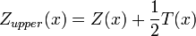
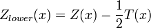
The camber of an airfoil can be defined by a camber line, which is the curve that is halfway between the upper and lower surfaces of the airfoil. Call this function Z(x). To fully define an airfoil we also a thickness function T(x), which describes the thickness of the airfoil at any given point. Then, the upper and lower surfaces can be defined as follows:
Source: Wikipedia (All text is available under the terms of the GNU Free Documentation License and Creative Commons Attribution-ShareAlike License.)
|


