|
Using "Student Power" to Generate Electricity to Run a Portable Compact Disc Player
Developers:
Jennifer Brittain
P.A. Guth Elementary School, Perkasie, PA
Mario Mirabelli
Senior Research Chemist, Rohm and Haas Company
Mark Silvano
Junior Research Chemist, Rohm and Haas Company
Frank Letterio
Laboratory Technician, Rohm and Haas Company
Grade Level:
3 through 6
Discipline:
Physical Science - Magnetism and Energy
Goals:
Upon completion of this unit, the student will:
- Conclude that magnets and magnetic fields can produce electricity.
- Understand how a small motor works.
- Understand how gears work.
- Describe how energy can transform along a pathway.
Pedal Powering the Compact Disk Player
Objectives:
Upon completion of this activity, the students will:
- Identify potential sources of energy.
- Describe the transformation of the energy of this system and ones similar.
Apparatus Description/Background:
The apparatus
pictured in Figure 1 is the one developed at the Rohm and Haas
Laboratory. For a technical explanation of this device and its
components, please see Appendix A. A simpler set up can also be created to achieve similar results. You will need a small motor and a gear box (see Appendix C)
mounted to something, like a piece of wood, which can be held or
C-clamped onto a table for stability. We assume that it may also be
possible to use a regular, geared bicycle. We used an adapted version
because the smaller set up seemed to make a lot of noise, therefore
making the CD less audible. The electric generator displayed in Figure
1 can produce a potential of approximately 3 volts or more when the
pedal is rotated at 40 revolutions/minute. This is the equivalent of
two dry cell alkaline batteries when placed in a series configuration
(nominal voltage of 1.5 volts/cell). Therefore, this generator is
limited to powering small direct current devices, which require a
maximum of two batteries. One device, which fits this requirement, is a
portable CD player. However, any device requiring one or two alkaline
batteries will suffice, especially if you are unable to overcome the
noise the device itself makes.
Background:
There are many
different forms of energy. These forms can be divided into six main
groups. These groups are mechanical energy, heat energy, electrical
energy, chemical energy, nuclear energy, and wave energy (like sound
energy and radiant energy). A simple example of how energy transforms
could start with the sun. The sun gives energy to the plants so they
can make their own food. When people or animals eat the plants they
receive the stored energy. People then use the energy they get from
plants to move things, like a crank. Here they are changing chemical
energy to mechanical energy. The crank is attached to the gears and a
generator, which changes the mechanical energy to electrical energy.
The electrical energy spins the CD player changing electrical energy
back into mechanical energy and radiant energy. Then they change into
wave energy (sound waves), and we are able to hear the music.
The generation
and transmission of energy from power plant to user involves many
transformations of energy. To produce electricity most power plants
burn fossil fuels like oil, natural gas, or coal. When these fuels are
burned the heat they produce is used to boil water. The boiling water
produces steam. This steam is then used to turn a turbine. These
turbines turn the coils, or magnets, of a generator to produce electric
current. (Any time a conducting material moves through a magnetic field
an electric field is generated in the conductor. If the conductor forms
part of a closed circuit, current will flow.) Transformers are then
used to increase or decrease the voltage of the current that travels
through the wires so it can travel long distances, and safely be used
in the home (the transformer step has been left out of the activity
that follows). Turbines could also be turned by wind, or falling water.
Investigation One - Transformation and Pathways of Energy
Activity One - Forms of Energy
Materials:
"bicycle generator", drawing paper, colored pencils or crayons
Procedure:
Involve the
students in the operation of the "bicycle generator". Hold a discussion
about the different forms of energy and where they could be applied to
the apparatus. Discuss the transformation through that pathway, then
have the student suggest similar examples. Have the students draw their
own example of a pathway. Be sure to have them also write about the
transformations that are taking place.
Have the students brainstorm ideas about how else the "bicycle generator" could be powered.
Activity Two- Pathway Game
Materials:
Pathway cards, Student Worksheet
Teacher Preparation:
When using groups
of four to six students, copy only one of the energy source pages per
group and 6 to 8 copies of the path cards. Cut the copied sheets into
uniform pieces. Each group will need a set of cards.
Procedure:
Discuss with
students the path that must be traveled in order to provide electricity
to their home. Place the students into groups of four, five, or six.
The number of students in the group will affect the cards that are
needed. The game is played like "Go Fish". There are four different
energy resources, and to start a pathway the student only needs one of
the four sources. To complete a pathway the student needs one each of
the rest of the cards. When a student collects all the cards of the
pathway in their hand. They may lay them down to win the game. However,
if they are unable to describe the transformations that are taking
place, they should not be declared a winner. Play should start over.
Observations/Discussion:
Students should complete worksheet when game play is concluded.
Worksheets:
Worksheets for Investigation 1 are available for download in PDF format:
Magnets and Electromagnets
Objectives:
Upon completion of this activity, the students will be able to:
- Identify magnetic materials.
- Explain that similar poles of a magnet repel and opposite poles attract each other.
- Describe how magnetism can be created in an electromagnet.
- Identify variables that effect the magnetism of an electromagnet.
- Identify devices that incorporate electromagnets.
Background:
Magnets that
exist in nature are called lodestones. Man-made magnets can be created
with materials that contain iron, steel, cobalt, and nickel. Scientists
believe that magnetism is due to the movement and alignment of the
electrons around the nucleus of an atom.
Temporary magnets
can be created from materials like soft iron by induction (by bringing
the material into proximity of a magnet, or having it touch a magnet),
by stroking it with a magnet in one direction to help align the
molecules, or by wrapping it with wire and attaching it to a dry cell.
The last example of a temporary magnet is called an electromagnet.
Electromagnets have a north-seeking and a south-seeking pole just like
other magnets, but these poles can be reversed if the electric current
is reversed. Electromagnets can also be strengthened by increasing the
amount of electrical current flowing through the wire, by increasing
the amount of turns of wire that are around the core, and by using a
U-shaped core. Electromagnets are used in many household devices like a
phone, many electrical appliances, and most electrical toys.
Investigation Two - Magnetic Forces
Set up several
experimental stations where the students can experiment with magnets or
do as a teacher demonstration. Below are some suggested activities.
Activity One - Determining Materials that are attracted to Magnets
Materials:
Magnets of
different shapes, sizes, and strengths; Materials to be tested - tacks,
brads, staples, rubber bands, aluminum foil, different coins
(especially old Canadian nickels, which have more nickel in them),
glass, chalk, etc., Student Worksheet.
Procedure:
Have the students try to pick up a variety of materials with magnets.
Observations/Discussion:
Have them record
their findings on the worksheet (What's Attractive) and make a
conclusion about them to be discussed with others.
Extensions
Have the students test their predictions about other materials from the conclusions on their worksheet.
Activity Two - Magnet Poles
Materials:
Magnets of
different shapes, sizes, and strengths, Iron filings (tacks or paper
clips may also be used and are not as messy), Student Worksheet.
Procedure:
Using the
different shaped magnets, have the students record where on the magnets
iron filing will stick to each by drawing a picture. Have them also
experiment to see where and how the magnets stick to each other.
Observations/Discussion:
Have the students write down a conclusion (Stick To It Worksheet) about their findings to be discussed with others.
Activity Three - How Magnet Poles Interact
Materials:
Ruler; String; Copper wire; Two magnets (per group) with color-coded or labeled (N or S) ends.
Procedure:
Attach the copper
wire to the magnet to form a balanced support where you can connect the
string so that the magnet may swing freely. Suspend that magnet away
from any metal objects by attaching the string to a ruler that can be
inserted into a stack of books. Label the poles by using different
colors and/or the letters N and S. Take another magnet (match the
colors/labels to the N and S poles of the suspended magnet) and have
the students try to spin the suspended magnet with out getting them
stuck together.
Observations/Discussion:
Have the students
write down a conclusion about how the ends of the magnets affect each
other to be discussed by the class. Students could use the color terms
at first, then replace them with the terms north-seeking and
south-seeking poles after further discussion.
See Appendix B for some great internet sites that have other magnet experiments and some additional background information.
Worksheets:
Worksheets for Investigation 2 are available for download in PDF format:
Investigation Three - Creating an Electromagnet
Materials:
Lantern battery
("D" size will work, but is harder to make safe connections); Paper
clips or tacks; 2 -3 feet of insulated copper wire; Soft iron nail
Procedure:
Expose the ends
of the copper wire. These ends should then be connected to some wire
clips and covered with electrical tape (the exposed wire heats up
quickly if left attached to the battery - this will also drain the
battery quickly if the connections are left attached). Wrap the wire
around the nail 5 times. Have the students attempt to attach the clips
or tacks and record their findings. Then wrap the nail with 10 coils of
wire and repeat. Continue this process, increasing the amount of coils
each time by 5 until you get to somewhere around 25 or 30.
Observations/Discussions:
Have the students
draw a conclusion about how the number of coils affect the strength of
the electromagnet. (Creating an Electromagnet Worksheet). Discuss the
variables which may affect each groups results (like battery strength,
quality of the coil, differences in weight of clips or tacks, placement
of those objects on the nail, etc...). Discuss ways to make an
electromagnet stronger (more batteries, more coils).
For similar experiments see Appendix B.
Extensions:
Examine how a nail may become magnetized without the current flow. Discuss ways to create and destroy magnetism in something.
Worksheets:
Worksheets for Investigation 3 are available for download in PDF format:
Simple Motor
Objectives:
Upon completion of this activity, the student will be able to:
- Identify the parts of a simple motor.
- Describe how electric energy is transformed to mechanical energy.
Background:
A motor is the
opposite of a generator since it turns electrical energy into
mechanical energy (see background from the section about transformation
and pathways), and uses electricity to produce magnetism.
Electromagnets are used in motors. Most motors have an armature,
commutator, permanent magnet, brushes and a power source. The motor
works in the following way. Current travels from the brushes to the
commutator, into the armature. The armature contains the coiled wire
and becomes the electromagnet. The north-seeking pole of the
electromagnet will be attracted to the south-seeking pole of the
permanent magnet causing the armature to move. When the armature
rotates it will eventually reach a position where the brushes lose,
then reestablish, contact with the commutator. This will then cause a
reverse in the current through the armature, and a reverse of its
poles. This reversing of current and changing of poles causes the motor
to continue to spin until the electrical current is removed.
Materials:
See Appendix B for some extensive background information about how motors work, and the steps to creating this small motor.
Procedure:
See Appendix B
for information on the construction of the motor. When creating the
motor here are some things we found that improved the motor:
Use a small gauge wire (20 -24 gauge).
Be sure that the coil is small and balanced.
Use a very strong magnet.
Use electrical tape instead of rubber bands.
Have patience!
Good luck! There are also many similar models for this motor, and even some commercially made kits.
Observations/Discussion:
Discuss with the students what work this motor could do.
Gears
Objectives:
Upon completion of this activity, the student will be able to:
- Identify how to calculate gear ratios.
- Explain the rationale for using gears.
Background:
The purpose of
using gears is to change the distance a bike, for example, moves
forward with each pedal stroke. The gear ratio of the "bicycle
generator" was calculated to be approximately 240 : 1. This means that
for every revolution of the generator pedal, the shaft will rotate 240
times. A normal bicycle tire is about 26 inches in diameter. By taking
the diameter of the wheel times _ you would be able to calculate the
circumference of the wheel which translates into the distance the bike
will travel. This activity will help the students get a feel for how
gears change the revolutions needed per minute to generate enough power
to run the CD player.
Investigation Four - Gear Ratio
Materials:
Five to seven geared bicycles (or may use one and do as a demonstration), Student Worksheet.
Procedures:
Have each bicycle
set to a different gear. Invert the bicycles. (The next step may be
skipped depending on the level of competency you feel your students
would have at remembering the starting and stopping point of the pedal
and the wheel at each station.) On the side of the back wheel of a
geared bicycle place a line, or bright colored tape, to establish a
starting point. Place a piece of tape on the floor under the wheel to
be lined up for the purpose of counting the revolutions. Place a
similar line on the floor straight under the pedal when the pedal is in
the down position.
Observations/Discussion:
Have the students
record the number of wheel turns associated with each pedal turn on the
worksheet. This sheet may need to be adapted to the level of the
students.
Extensions:
Find the circumference of each tire and calculate the distance the bicycle would travel.
Worksheets:
Worksheets for Investigation 4 are available for download in PDF format:
Appendix A
Technical Explanation of the Construction of the Electric Generator
The electric
generator utilized in this experiment was constructed from a modified
stationary exercise bicycle coupled to a simple DC electric motor
(Figure 1). By rotating the shaft of the electric motor, a potential
difference (voltage) is created at the positive and negative leads,
which can be used to power a portable DC device. In order to achieve
the necessary rotation of the motor shaft (for the motors that we
tested, a shaft rotation speed of 5000-10,000 rpm was necessary in
order to achieve a voltage of 3 volts), the motor is attached to a
gearbox and coupled to the flywheel of the stationary bicycle (Figure
1). Attaching the motor in this manner allows for a higher gear ratio,
thus reducing the necessary rotation speed of the bicycle pedal to a
more manageable level.
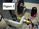
For the device in
Figure 2, the motor is directly coupled to a 2.5:1 gearbox, which is in
contact with an 8.25-inch flywheel. The gearbox shaft contacts the
bicycle flywheel via a battery terminal nut, which was bored out to fit
over the gearbox shaft. The knurled section of the battery terminal nut
was grooved to facilitate an O-ring ("tire") while the entire device is
held onto the shaft with a setscrew. The flywheel is attached to the
bike pedal via a separate gearbox (~6:1 gear ratio) which results in an
overall gear ratio of approximately 240:1.
There are many
possible variations to the apparatus described above. One can envision
utilizing a geared bicycle in an inverted position and contacting the
bicycle wheel with the output shaft of the motor gearbox (as described
above). The gear ratio can be conveniently changed using the bicycle
derailleur and the bicycle could be hand cranked to provide the power.
Operation of a Portable CD Player.
The CD player was
modified to accept alligator clip connectors so that easy connections
could be made to the motor. The positive and negative terminals of the
motor were connected to the positive and negative terminals of the CD
player (found in the battery compartment). It is important to ensure
that the polarity of the circuit is correct; some devices can be
damaged if set up in the reverse direction. In addition, it is
important to determine the proper rotation direction on the pedal. Only
rotation in one direction (clockwise or counter clockwise) will produce
a positive voltage. Rotation in the other direction will produce a
negative voltage and some control procedure should be put in place to
prevent exposure of the electronic device to a negative voltage. Once
these connections are secured, a second set of alligator clips is
fastened to the motor terminals in order to attach a digital voltmeter.
This voltmeter is a necessary component of this system. The digital
voltmeter allows the operator of the system a visual display of the
applied voltage, thus aiding in determining and maintaining the proper
rotation rate. The CD player will only operate when the external
voltage is within a range of 2.2-3.2 volts. A voltage of less than 2.2
volts or greater than 3.2 volts results in disruption of sound,
requiring a complete restart of the system.
Once the
electrical connections have been made and the proper direction of
rotation has been determined, the unit is ready for operation. While
headphones can be used to listen to the music, a small set of amplified
computer speakers would be more appropriate for a classroom
demonstration. Place a CD into the unit and begin rotating the pedal
until a voltage of approximately 2.5-3.0 volts is achieved and
maintained (Note: Some portable CD players are equipped with a
separate on-off power switch. If this is the case, the voltage must be
applied to the unit prior to turning it on.) Once the external
voltage is maintained in the desired range, hit the "Play" button and
enjoy your favorite music. As long as the pedal is turning, the music
will play.
Appendix B
Internet Resources:
Magnet Experiments
https://www.juliantrubin.com/fairprojects/electricity/magnetism.html
http://www.lessonplanspage.com/index.html
http://www.school-for-champions.com/science/magnetism.htm
Electromagnets
https://www.juliantrubin.com/fairprojects/electricity/electromagnetism.html
http://www.howstuffworks.com/electromagnet.htm
How a Motor Works
http://www.howstuffworks.com/motor.htm
Building a Simple Motor
Gears
http://www.howstuffworks.com/gears.htm
Textbooks
Victor, Edward. Science for the Elementary School. New York: Macmillan Publishing Company, 1985. 768 pp.
Addison-Wesley Science, Sixth Grade Edition, 1989.
Commercial Kits
Adventures in Science - Magnetism from Educational Insights
Electro-Magnetix from Educational Design, Inc.
Appendix C
Resources
Radio Shack and Hobby Shops
Delta Education - http://www.delta-education.com / 1-800-801-7083
Fisher Scientific Company - http://www.fishersci.com / Fax: 412-490-8304
Science Stuff - http://www.sciencestuff.com / 1-800-795-7315
This experiment is courtesy of 
|
|
|
|