Definition
A capacitor is an electrical device that can store energy in the electric field between a pair of conductors.
Capacitance is the ability of a body to hold an electrical charge.
Basics
See also: Variable Capacitor
A capacitor is an electrical/electronic device that can store energy in the electric field between a pair of conductors (called "plates"). The process of storing energy in the capacitor is known as "charging", and involves electric charges of equal magnitude, but opposite polarity, building up on each plate.
Capacitors are often used in electrical circuit and electronic circuits as energy-storage devices. They can also be used to differentiate between high-frequency and low-frequency signals. This property makes them useful in electronic filters.
Capacitors are occasionally referred to as condensers. This is considered an antiquated term in English, but most other languages use an equivalent, like the German word "Kondensator".
History
Various types of capacitors. From left: multilayer ceramic, ceramic
disc, multilayer polyester film, tubular ceramic, polystyrene,
metallized polyester film, aluminium electrolytic. Major scale
divisions are cm.
In October 1745, Ewald Georg von Kleist of Pomerania
invented the first recorded capacitor: a glass jar coated inside and
out with metal. The inner coating was connected to a rod that passed
through the lid and ended in a metal sphere. By having this thin layer
of glass insulation (a dielectric) between two large, closely spaced
plates, von Kleist found the energy density could be increased dramatically compared with the situation with no insulator.
In January 1746, before Kleist's discovery became widely known, a Dutch physicist Pieter van Musschenbroek independently invented a very similar capacitor. It was named the Leyden jar, after the University of Leyden
where van Musschenbroek worked. Daniel Gralath was the first to combine
several jars in parallel into a "battery" to increase the total
possible stored charge.
The earliest unit of capacitance was the 'jar', equivalent to about 1 nF.
Early capacitors were also known as condensers, a term that is still occasionally used today. It was coined by Alessandro Volta in 1782 (derived from the Italian condensatore),
with reference to the device's ability to store a higher density of
electric charge than a normal isolated conductor. Most non-English
languages still use a word derived from "condensatore", as the 'in
other languages' links from this article testify.
Physics
A capacitor consists of two conductive electrodes, or plates, separated by a dielectric.
Capacitance
The capacitor's capacitance (C) is a measure of the amount of charge (Q) stored on each plate for a given potential difference or voltage (V) which appears between the plates:

In SI units, a capacitor has a capacitance of one farad when one coulomb of charge is stored due to one volt
applied potential difference across the plates. Since the farad is a
very large unit, values of capacitors are usually expressed in
microfarads (µF), nanofarads (nF), or picofarads (pF).
When there is a difference in electric charge between the plates, an electric field
is created in the region between the plates that is proportional to the
amount of charge that has been moved from one plate to the other. This
electric field creates a potential difference V = E·d between the plates of this simple parallel-plate capacitor.
The capacitance is proportional to the surface area of the
conducting plate and inversely proportional to the distance between the
plates. It is also proportional to the permittivity of the dielectric (that is, non-conducting) substance that separates the plates.
The capacitance of a parallel-plate capacitor is given by:

where ε is the permittivity of the dielectric, A is the area of the plates and d is the spacing between them.
In the diagram, the rotated molecules create an opposing electric
field that partially cancels the field created by the plates, a process
called dielectric polarization.
Stored energy
As opposite charges accumulate on the plates of a capacitor due to
the separation of charge, a voltage develops across the capacitor due
to the electric field of these charges. Ever-increasing work must be
done against this ever-increasing electric field as more charge is
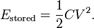
separated. The energy (measured in joules, in SI)
stored in a capacitor is equal to the amount of work required to
establish the voltage across the capacitor, and therefore the electric
field. The energy stored is given by:

where V is the voltage across the capacitor.
The maximum energy that can be (safely) stored in a particular
capacitor is limited by the maximum electric field that the dielectric
can withstand before it breaks down. Therefore, all capacitors made
with the same dielectric have about the same maximum energy density (joules of energy per cubic meter).
Hydraulic model
As electrical circuitry can be modeled by fluid flow, a capacitor can be modeled as a chamber with a flexible diaphragm
separating the input from the output. As can be determined intuitively
as well as mathematically, this provides the correct characteristics:
- The pressure difference (voltage difference) across the unit is proportional to the integral of the flow (current)
- A steady state
current cannot pass through it because the pressure will build up
across the diaphragm until it equally opposes the source pressure.
- But a transient pulse or alternating current can be transmitted
- The capacitance of units connected in parallel is equivalent to the sum of their individual capacitances
Electrical circuits
The electrons within dielectric molecules are influenced by the
electric field, causing the molecules to rotate slightly from their
equilibrium positions. The air gap is shown for clarity; in a real
capacitor, the dielectric is in direct contact with the plates.
Capacitors also allow AC current to flow and block DC current.
DC sources
The dielectric between the plates is an insulator and blocks the
flow of electrons. A steady current through a capacitor deposits
electrons on one plate and removes the same quantity of electrons from
the other plate. This process is commonly called 'charging' the
capacitor. The current through the capacitor results in the separation
of electric charge within the capacitor, which develops an electric
field between the plates of the capacitor, equivalently, developing a
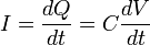
voltage difference between the plates. This voltage V is directly
proportional to the amount of charge separated Q. Since the current I
through the capacitor is the rate at which charge Q is forced through
the capacitor (dQ/dt), this can be expressed mathematically as:
-
 |
|
where
- I is the current flowing in the conventional direction, measured in amperes,
- dV/dt is the time derivative of voltage, measured in volts per second, and
- C is the capacitance in farads.
|
|
For circuits with a constant (DC) voltage source and consisting of
only resistors and capacitors, the voltage across the capacitor cannot
exceed the voltage of the source. Thus, an equilibrium is reached where
the voltage across the capacitor is constant and the current through
the capacitor is zero. For this reason, it is commonly said that
capacitors block DC.
AC sources
The current through a capacitor due to an AC
source reverses direction periodically. That is, the alternating
current alternately charges the plates: first in one direction and then
the other. With the exception of the instant that the current changes
direction, the capacitor current is non-zero at all times during a
cycle. For this reason, it is commonly said that capacitors "pass" AC.
However, at no time do electrons actually cross between the plates,
unless the dielectric breaks down. Such a situation would involve
physical damage to the capacitor and likely to the circuit involved as
well.
Since the voltage across a capacitor is proportional to the integral
of the current, as shown above, with sine waves in AC or signal
circuits this results in a phase difference of 90 degrees, the current
leading the voltage phase angle. It can be shown that the AC voltage
across the capacitor is in quadrature
with the alternating current through the capacitor. That is, the
voltage and current are 'out-of-phase' by a quarter cycle. The
amplitude of the voltage depends on the amplitude of the current
divided by the product of the frequency of the current with the
capacitance, C.
Impedance
The ratio of the phasor voltage across a circuit element to the phasor current through that element is called the impedance Z. For a capacitor, the impedance is given by

where
 is the capacitive reactance, is the capacitive reactance, is the angular frequency, is the angular frequency,- f is the frequency),
- C is the capacitance in farads, and
- j is the imaginary unit.
While this relation (between the frequency domain voltage and current associated with a capacitor) is always true, the ratio of the time domain voltage and current amplitudes is equal to XC only for sinusoidal (AC) circuits in steady state.
See derivation Deriving capacitor impedance.
Hence, capacitive reactance is the negative imaginary component of
impedance. The negative sign indicates that the current leads the
voltage by 90° for a sinusoidal signal, as opposed to the inductor,
where the current lags the voltage by 90°.
The impedance is analogous to the resistance of a resistor. The impedance of a capacitor is inversely proportional
to the frequency -- that is, for very high-frequency alternating
currents the reactance approaches zero -- so that a capacitor is nearly
a short circuit
to a very high frequency AC source. Conversely, for very low frequency
alternating currents, the reactance increases without bound so that a
capacitor is nearly an open circuit to a very low frequency AC source.
This frequency dependent behaviour accounts for most uses of the
capacitor.
Reactance is so called because the capacitor doesn't dissipate
power, but merely stores energy. In electrical circuits, as in
mechanics, there are two types of load, resistive and reactive.
Resistive loads (analogous to an object sliding on a rough surface)
dissipate the energy delivered by the circuit as heat, while reactive
loads (analogous to a spring or frictionless moving object) store this
energy, ultimately delivering the energy back to the circuit.
Also significant is that the impedance is inversely proportional to
the capacitance, unlike resistors and inductors for which impedances
are linearly proportional to resistance and inductance respectively.
This is why the series and shunt impedance formulae (given below) are
the inverse of the resistive case. In series, impedances sum. In
parallel, conductances sum.
Laplace equivalent (s-domain)
When using the Laplace transform in circuit analysis, the capacitive impedance is represented in the s domain by:

where C is the capacitance, and s (= σ+jω) is the complex frequency.
Displacement current
The physicist James Clerk Maxwell invented the concept of displacement current, dD/dt, to make Ampère's law
consistent with conservation of charge in cases where charge is
accumulating as in a capacitor. He interpreted this as a real motion of
charges, even in vacuum, where he supposed that it corresponded to
motion of dipole charges in the aether. Although this interpretation has been abandoned, Maxwell's correction to Ampère's law remains valid.
Networks
Series or parallel arrangements
Capacitors in a parallel configuration each have the same potential difference (voltage). Their total capacitance (Ceq) is given by:


The reason for putting capacitors in parallel is to increase the
total amount of charge stored. In other words, increasing the
capacitance also increases the amount of energy that can be stored. Its
expression is:
The current through capacitors in series
stays the same, but the voltage across each capacitor can be different.
The sum of the potential differences (voltage) is equal to the total
voltage. Their total capacitance is given by:


In parallel the effective area of the combined capacitor has
increased, increasing the overall capacitance. While in series, the
distance between the plates has effectively been increased, reducing
the overall capacitance.
In practice capacitors will be placed in series as a means of
economically obtaining very high voltage capacitors, for example for
smoothing ripples in a high voltage power supply. Three "600 volt
maximum" capacitors in series, will increase their overall working
voltage to 1800 volts. This is of course offset by the capacitance
obtained being only one third of the value of the capacitors used. This
can be countered by connecting 3 of these series set-ups in parallel,
resulting in a 3x3 matrix of capacitors with the same overall
capacitance as an individual capacitor but operable under three times
the voltage. In this application, a large resistor
would be connected across each capacitor to ensure that the total
voltage is divided equally across each capacitor and also to discharge
the capacitors for safety when the equipment is not in use.
Another application is for use of polarized capacitors in
alternating current circuits; the capacitors are connected in series,
in reverse polarity, so that at any given time one of the capacitors is
not conducting...
Capacitor/inductor duality
In mathematical terms, the ideal capacitor can be considered as an inverse of the ideal inductor,
because the voltage-current equations of the two devices can be
transformed into one another by exchanging the voltage and current
terms. Just as two or more inductors can be magnetically coupled to
make a transformer, two or more charged conductors can be electrostatically coupled to make a capacitor. The mutual capacitance
of two conductors is defined as the current that flows in one when the
voltage across the other changes by unit voltage in unit time.
Capacitor types
Listed by di-electric material.
-
A 12 pF 20 kV fixed vacuum capacitor
Vacuum :
Two metal, usually copper, electrodes are separated by a vacuum. The
insulating envelope is usually glass or ceramic. Typically of low
capacitance - 10 - 1000 pF and high voltage, up to tens of kilovolts,
they are most often used in radio transmitters and other high voltage
power devices. Both fixed and variable types are available. Vacuum variable capacitors
can have a minimum to maximum capacitance ratio of up to 100, allowing
any tuned circuit to cover a full decade of frequency. Vacuum is the
most perfect of dielectrics with a zero loss tangent. This allows very
high powers to be transmitted without significant loss and consequent
heating.
- Air : Air dielectric capacitors consist of metal plates
separated by an air gap. The metal plates, of which there may be many
interleaved, are most often made of aluminium or silver-plated brass.
Nearly all air dielectric capacitors are variable and are used in radio
tuning circuits.
- Metallized plastic film: Made from high quality polymer film (usually polycarbonate, polystyrene, polypropylene, polyester (Mylar), and for high quality capacitors polysulfone),
and metal foil or a layer of metal deposited on surface. They have good
quality and stability, and are suitable for timer circuits. Suitable
for high frequencies.
- Mica: Similar to metal film. Often high voltage. Suitable for high frequencies. Expensive. Excellent tolerance.
- Paper: Used for relatively high voltages. Now obsolete.
- Glass: Used for high voltages. Expensive. Stable temperature coefficient in a wide range of temperatures.
- Ceramic: Chips of alternating layers of metal and ceramic. Depending on their dielectric, whether Class 1 or Class 2, their degree of temperature/capacity dependence varies. They often have (especially the class 2) high dissipation factor,
high frequency coefficient of dissipation, their capacity depends on
applied voltage, and their capacity changes with aging. However they
find massive use in common low-precision coupling and filtering
applications. Suitable for high frequencies.
- Aluminum electrolytic:
Polarized. Constructionally similar to metal film, but the electrodes
are made of etched aluminium to acquire much larger surfaces. The
dielectric is soaked with liquid electrolyte.
They can achieve high capacities but suffer from poor tolerances, high
instability, gradual loss of capacity especially when subjected to
heat, and high leakage. Tend to lose capacity in low temperatures. Bad
frequency characteristics make them unsuited for high-frequency
applications. Special types with low equivalent series resistance are available.
- Tantalum electrolytic:
Similar to the aluminum electrolytic capacitor but with better
frequency and temperature characteristics. High dielectric absorption.
High leakage. Has much better performance at low temperatures.
- OS-CON
(or OC-CON) capacitors are a polymerized organic semiconductor
solid-electrolyte type that offer longer life at higher cost than
standard electrolytics.
- Supercapacitors: Made from carbon aerogel, carbon nanotubes, or highly porous electrode materials. Extremely high capacity. Can be used in some applications instead of rechargeable batteries.
- Gimmick capacitors are capacitors made from two insulated
wires that have been twisted together. Each wire forms a capacitor
plate. Gimmick capacitors are also a form of variable capacitor. Small
changes in capacitance (20 percent or less) are obtained by twisting
and untwisting the two wires.
- Varactors or varicap capacitors are specialized, reverse-biased diodes whose capacitance varies with voltage. Used in phase-locked loops, amongst other applications.
Applications
Capacitors have various uses in electronic and electrical systems.
Energy storage
A capacitor can store electric energy when disconnected from its charging circuit, so it can be used like a temporary battery.
Capacitors are commonly used in electronic devices to maintain power
supply while batteries are being changed. (This prevents loss of
information in volatile memory.)
Power conditioning
Capacitors are used in power supplies where they smooth the output of a full or half wave rectifier. They can also be used in charge pump circuits as the energy storage element in the generation of higher voltages than the input voltage.
Capacitors are connected in parallel with the power circuits of most
electronic devices and larger systems (such as factories) to shunt away
and conceal current fluctuations from the primary power source to
provide a "clean" power supply for signal or control circuits. Audio
equipment, for example, uses several capacitors in this way, to shunt
away power line hum before it gets into the signal circuitry. The
capacitors act as a local reserve for the DC power source, and bypass
AC currents from the power supply. This is used in car audio applications, when a stiffening capacitor compensates for the inductance and resistance of the leads to the lead-acid car battery.
Power factor correction
Capacitors are used in power factor correction. Such capacitors often come as three capacitors connected as a three phase load. Usually, the values of these capacitors are given not in farads but rather as a reactive power in volt-amperes reactive (VAr). The purpose is to counteract inductive loading from electric motors and fluorescent lighting in order to make the load appear to be mostly resistive.
Filtering
Signal de-coupling
Because capacitors pass AC but block DC signals
(when charged up to the applied dc voltage), they are often used to
separate the AC and DC components of a signal. This method is known as AC de-coupling. Here, a large value of capacitance, whose value need not be accurately controlled, but whose reactance is small at the signal frequency, is employed.
Noise filters, motor starters, and snubbers
When an inductive circuit is opened, the current through the
inductance collapses quickly, creating a large voltage across the open
circuit of the switch or relay. If the inductance is large enough, the
energy will generate a spark, causing the contact points to oxidize,
deteriorate, or sometimes weld together, or destroying a solid-state
switch. A snubber
capacitor across the newly opened circuit creates a path for this
impulse to bypass the contact points, thereby preserving their life;
these were commonly found in contact breaker ignition systems, for instance. Similarly, in smaller scale circuits, the spark may not be enough to damage the switch but will still radiate undesirable radio frequency interference (RFI), which a filter
capacitor absorbs. Snubber capacitors are usually employed with a
low-value resistor in series, to dissipate energy and minimize RFI.
Such resistor-capacitor combinations are available in a single package.
In an inverse fashion, to initiate current quickly through an
inductive circuit requires a greater voltage than required to maintain
it; in uses such as large motors, this can cause undesirable startup
characteristics, and a motor starting capacitor is used to increase the coil current to help start the motor.
Capacitors are also used in parallel to interrupt units of a high-voltage circuit breaker in order to equally distribute the voltage between these units. In this case they are called grading capacitors.
In schematic diagrams, a capacitor used primarily for DC charge
storage is often drawn vertically in circuit diagrams with the lower,
more negative, plate drawn as an arc. The straight plate indicates the
positive terminal of the device, if it is polarized.
Signal processing
The energy stored in a capacitor can be used to represent information, either in binary form, as in DRAMs, or in analogue form, as in analog sampled filters and CCDs. Capacitors can be used in analog circuits as components of integrators or more complex filters and in negative feedback loop stabilization. Signal processing circuits also use capacitors to integrate a current signal.
Tuned circuits
Capacitors and inductors are applied together in tuned circuits
to select information in particular frequency bands. For example, radio
receivers rely on variable capacitors to tune the station frequency.
Speakers use passive analog crossovers, and analog equalizers use
capacitors to select different audio bands.
In a tuned circuit such as a radio receiver, the frequency selected is a function of the inductance (L) and the capacitance (C) in series, and is given by:
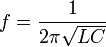
This is the frequency at which resonance occurs in an LC circuit.
Other applications
Sensing
Most capacitors are designed to maintain a fixed physical structure.
However, various things can change the structure of the capacitor — the
resulting change in capacitance can be used to sense those things.
Changing the dielectric: the effects of varying the physical and/or electrical characteristics of the dielectric can also be of use. Capacitors with an exposed and porous dielectric can be used to measure humidity in air.
Changing the distance between the plates: Capacitors are used to accurately measure the fuel level in airplanes. Capacitors with a flexible plate can be used to measure strain or pressure. Capacitors are used as the sensor in condenser microphones, where one plate is moved by air pressure, relative to the fixed position of the other plate. Some accelerometers use MEMS
capacitors etched on a chip to measure the magnitude and direction of
the acceleration vector. They are used to detect changes in
acceleration, eg. as tilt sensors or to detect free fall, as sensors
triggering airbag deployment, and in many other applications. Also some fingerprint sensors. Additionally, a user can adjust the pitch of a theremin musical instrument by moving his hand since this changes the effective capacitance between the user's hand and the antenna.
Changing the effective area of the plates: capacitive touch switches.
Pulsed power and weapons
Groups of large, specially constructed, low-inductance high-voltage capacitors (capacitor banks) are used to supply huge pulses of current for many pulsed power applications. These include electromagnetic forming, Marx generators, pulsed lasers (especially TEA lasers), pulse forming networks, radar, fusion research, and particle accelerators.
Large capacitor banks(Reservoir) are used as energy sources for the exploding-bridgewire detonators or slapper detonators in nuclear weapons and other specialty weapons. Experimental work is under way using banks of capacitors as power sources for electromagnetic armour and electromagnetic railguns or coilguns.
See also Explosively pumped flux compression generator.
Hazards and safety
Capacitors may retain a charge long after power is removed from a
circuit; this charge can cause shocks (sometimes fatal) or damage to
connected equipment. For example, even a seemingly innocuous device
such as a disposable camera flash unit powered by a 1.5 volt AA battery contains a capacitor which may be charged to over 300 volts. This is easily capable of delivering an extremely painful shock.
Care must be taken to ensure that any large or high-voltage
capacitor is properly discharged before servicing the containing
equipment. For board-level capacitors, this is done by placing a bleeder resistor
across the terminals, whose resistance is large enough that the leakage
current will not affect the circuit, but small enough to discharge the
capacitor shortly after power is removed. High-voltage capacitors
should be stored with the terminals shorted, since temporarily discharged capacitors can develop potentially dangerous voltages when the terminals are left open-circuited.
Large oil-filled old capacitors must be disposed of properly as some contain polychlorinated biphenyls (PCBs). It is known that waste PCBs can leak into groundwater under landfills. If consumed by drinking contaminated water, PCBs are carcinogenic,
even in very tiny amounts. If the capacitor is physically large it is
more likely to be dangerous and may require precautions in addition to
those described above. New electrical components are no longer produced
with PCBs. ("PCB" in electronics usually means printed circuit board,
but the above usage is an exception.) Capacitors containing PCB were
labelled as containing "Askarel" and several other trade names.
High-voltage
Above and beyond usual hazards associated with working with high
voltage, high energy circuits, there are a number of dangers that are
specific to high voltage capacitors. High voltage capacitors may
catastrophically fail when subjected to voltages or currents beyond
their rating, or as they reach their normal end of life. Dielectric or
metal interconnection failures may create arcing called an arc fault,
within oil-filled units that vaporizes dielectric fluid, resulting in
case bulging, rupture, or even an explosion
that disperses flammable oil, starts fires, and damages nearby
equipment, called flash - melt down, Rigid cased cylindrical glass or
plastic cases are more prone to explosive rupture than rectangular
cases due to an inability to easily expand under pressure. Capacitors
used in RF or sustained high current applications can overheat,
especially in the center of the capacitor rolls. The trapped heat may
cause rapid interior heating and destruction, even though the outer
case remains relatively cool. Capacitors used within high energy
capacitor banks can violently explode when a fault in one capacitor
causes sudden dumping of energy stored in the rest of the bank into the
failing unit. And, high voltage vacuum capacitors can generate soft
X-rays even during normal operation. Proper containment, fusing, and
preventative maintenance can help to minimize these hazards.
High voltage capacitors can benefit from a pre-charge
to limit in-rush currents at power-up of HVDC circuits. This will
extend the life of the component and may mitigate high voltage hazards.
Source: Wikipedia (All text is available under the terms of the GNU Free Documentation License and Creative Commons Attribution-ShareAlike License.)
|


