Definitions
Multipath is the propagation phenomenon that results in radio signals' reaching the receiving antenna by two or more paths.
Fading refers to the distortion that a carrier-modulated telecommunication signal experiences over certain propagation media. In wireless systems, fading is due to multipath propagation and is sometimes referred to as multipath induced fading.
Multipath
In wireless telecommunications, multipath is the propagation phenomenon that results in radio signals' reaching the receiving antenna by two or more paths. Causes of multipath include atmospheric ducting, ionospheric reflection and refraction, and reflection from terrestrial objects, such as mountains and buildings.
The effects of multipath include constructive and destructive interference, and phase shifting of the signal. This causes Rayleigh fading, named after Lord Rayleigh. The standard statistical model of this gives a distribution known as the Rayleigh distribution.
Rayleigh fading with a strong line of sight content is said to have a Rician distribution, or to be Rician fading.
In facsimile and television transmission, multipath causes jitter and ghosting,
seen as a faded duplicate image to the right of the main image. Ghosts
occur when transmissions bounce off a mountain or other large object,
while also arriving at the antenna by a shorter, direct route, with the
receiver picking up two signals separated by a delay.
In radar processing, multipath causes ghost targets to appear, deceiving the radar receiver.
These ghosts are particularly bothersome since they move and behave
like the normal targets (which they echo), and so the receiver has
difficulty in isolating the correct target echo. These problems can be
overcome by incorporating a ground map of the radar's surroundings and
eliminating all echoes which appear to originate below ground or above
a certain height.
In digital radio communications (such as GSM) multipath can cause errors and affect the quality of communications. The errors are due to Intersymbol interference (ISI). Equalisers are often used to correct the ISI. Alternatively, techniques such as orthogonal frequency division modulation and Rake receivers may be used.
Mathematical modeling
The mathematical model of the multipath can be presented using the method of the impulse response used for studying linear systems.
Suppose to transmit a single, ideal Dirac pulse of electromagnetic power at time 0, i.e.
x(t) = δ(t)
At the receiver, due to the presence of the multiple electromagnetic
paths, more than one pulse will be received (we suppose here that the channel has infinite bandwidth,
thus the pulse shape is not modified at all), and each one of them will
arrive at different times. In fact, since the electromagnetic signals
travel at the speed of light,
and since every path has a geometrical length possibly different from
that of the other ones, there are different air travelling times
(consider that, in free space, the light takes 3μs to cross a 1km span). Thus, the received signal will be expressed by
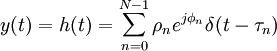
where N is the number of received impulses (equivalent to the number of electromagnetic paths, and possibly very large), τn is the time delay of the generic nth impulse, and  represent the complex amplitude (i.e., magnitude and phase) of the generic received pulse. As a consequence, y(t) also represents the impulse response function h(t) of the equivalent multipath model. represent the complex amplitude (i.e., magnitude and phase) of the generic received pulse. As a consequence, y(t) also represents the impulse response function h(t) of the equivalent multipath model.
More in general, in presence of time variation of the geometrical
reflection conditions, this impulse response is time varying, and as
such we have
τn = τn(t)
ρn = ρn(t)
φn = φn(t)
Very often, just one parameter is used to denote the severity of multipath conditions: it is called the multipath time, TM, and it is defined as the time delay existing between the first and the last received impulses
TM = τN − 1 − τ0
In practical conditions and measurement, the multipath time is
computed by considering as last impulse the first one which allows to
receive a determined amount of the total transmitted power (scaled by
the atmospheric and propagation losses), e.g. 99%.
Keeping our aim at linear, time invariant systems, we can also
characterize the multipath phenomenon by the channel transfer function H(f), which is defined as the continuous time Fourier transform of the impulse response h(t)
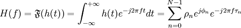
where the last right-hand term of the previous equation is easily
obtained by remembering that the Fourier transform of a Dirac is a
complex exponential function, an eigenfunction of every linear system.
The obtained channel transfer characteristic has a typical appearance of a sequence of peaks and valleys (also called notches);
it can be shown that, on average, the distance (in Hz) between two
consecutive valleys (or two consecutive peaks), is roughly inversely
proportional to the multipath time. The so-called coherence bandwidth is thus defined as

For example, with a multipath time of 3μs (corresponding to a 1 km
of added on-air travel for the last received impulse), there is a
coherence bandwidth of about 330 kHz.
Fading
Fading refers to the distortion that a carrier-modulated telecommunication signal experiences over certain propagation media. A fading channel is a communication channel that experiences fading. In wireless systems, fading is due to multipath propagation and is sometimes referred to as multipath induced fading.
Key Concepts
In wireless communications, the presence of reflectors in the
environment surrounding a transmitter and receiver create multiple
paths that a transmitted signal can traverse. As a result, the receiver
sees the superposition
of multiple copies of the transmitted signal, each traversing a
different path. Each signal copy will experienced differences in attenuation, delay and phase shift
while travelling from the source to the receiver. This can result in
either constructive or destructive interference, amplifying or
attenuating the signal power seen at the receiver. Strong destructive
interference is frequently referred to as a deep fade and may result in temporary failure of communication due to a severe drop in the channel signal-to-noise ratio.
A common example of multipath fading is the experience of stopping
at a traffic light and hearing an FM broadcast degenerate into static,
while the signal is re-acquired if the vehicle moves only a fraction of
a meter. The loss of the broadcast is caused by the vehicle stopping at
a point where the signal experienced severe destructive interference.
Cellular phones can also exhibit similar momentary fades.
Fading channel models are often used to model the effects of
electromagnetic transmission of information over the air in cellular
networks and broadcast communication. Fading channel models are also
used in underwater acoustic communications to model the distortion
caused by the water. Mathematically, fading is usually modeled as a
time-varying random change in the amplitude and phase of the transmitted signal.
Slow vs. Fast Fading
The terms slow and fast fading refer to the rate at which the magnitude and phase change imposed by the channel on the signal changes. The coherence time
is a measure of the minimum time required for the magnitude change of
the channel to become decorrelated from its previous value.
- Slow fading arises when the coherence time of the channel is
large relative to the delay constraint of the channel. In this regime,
the amplitude and phase change imposed by the channel can be considered
roughly constant over the period of use. Slow fading can be caused by
events such as shadowing, where a large obstruction such as a
hill or large building obscures the main signal path between the
transmitter and the receiver. The amplitude change caused by shadowing
is often modeled using a log-normal distribution with a standard deviation according to the Log Distance Path Loss Model.
- Fast Fading occurs when the coherence time of the channel is
small relative to the delay constraint of the channel. In this regime,
the amplitude and phase change imposed by the channel varies
considerably over the period of use.
In a fast-fading channel, the transmitter may take advantage of the variations in the channel conditions using time diversity
to help increase robustness of the communication to a temporary deep
fade. Although a deep fade may temporarily erase some of the
information transmitted, use of an error-correcting code
coupled with successfully transmitted bits during other time instances
can allow for the erased bits to be recovered. In a slow-fading
channel, it is not possible to use time diversity because the
transmitter sees only a single realization of the channel within its
delay constraint. A deep fade therefore lasts the entire duration of
transmission and cannot be mitigated using coding.
The coherence time of the channel is related to a quantity known as the Doppler spread
of the channel. When a user (or reflectors in its environment) is
moving, the user's velocity causes a shift in the frequency of the
signal transmitted along each signal path. This phenomenon is known as
the Doppler shift.
Signals travelling along different paths can have different Doppler
shifts, corresponding to different rates of change in phase. The
difference in Doppler shifts between different signal components
contributing to a single fading channel tap is known as the Doppler
spread. Channels with a large Doppler spread have signal components
that are each changing independently in phase over time. Since fading
depends on whether signal components add constructively or
destructively, such channels have a very short coherence time.
In general, coherence time is inversely related to Doppler spread, typically expressed as:

where Tc is the coherence time, Ds is the Doppler spread, and k is a constant taking on values in the range of 0.25 to 0.5.
Flat vs. Frequency-selective Fading
As the carrier frequency of a signal is varied, the magnitude of the change in amplitude will vary. The coherence bandwidth measures the minimum separation in frequency after which two signals will experience uncorrelated fading.
- In flat fading, the coherence bandwidth of the channel is
larger than the bandwidth of the signal. Therefore, all frequency
components of the signal will experience the same magnitude of fading.
- In frequency-selective fading, the coherence bandwidth of
the channel is smaller than the bandwidth of the signal. Different
frequency components of the signal therefore experience decorrelated
fading.
In a frequency-selective fading channel, since different frequency
components of the signal are affected independently, it is highly
unlikely that all parts of the signal will be simultaneously affected
by a deep fade. Certain modulation schemes such as OFDM and CDMA
are well-suited to employing frequency diversity to provide robustness
to fading. OFDM divides the wideband signal into many slowly modulated
narrowband subcarriers, each exposed to flat fading rather than
frequency selective fading. This can be combated by means of error coding, simple equalization or adaptive bit loading. Inter-symbol interference is avoided by introducing a guard interval between the symbols. CDMA uses the Rake receiver to deal with each echo separately.
Frequency-selective fading channels are also dispersive, in that the
signal energy associated with each symbol is spread out in time. This
causes transmitted symbols that are adjacent in time to interfere with
each other. Equalizers are often deployed in such channels to compensate for the effects of the intersymbol interference.
Fading Models
Examples of fading models for the distribution of the attenuation are:
- Nakagami fading
- Weibull fading
- Rayleigh fading
- Rician fading
- Dispersive fading models, with several echoes, each exposed to
different delay, gain and phase shift, often constant.This results in
frequency selective fading and inter-symbol interference. The gains may
be Rayleigh or Rician distributed.The echoes may also be exposed to doppler-shift, resulting in a time varying channel model.
- Log-normal shadow fading
Mitigation
Fundamentally, fading causes poor performance in traditional
communication systems because the quality of the communications link
depends on a single path or channel, and due to fading there is a
significant probability that the channel will experience a deep fade.
The probability of experiencing a fade (and associated bit errors as
the signal-to-noise ratio drops) on the channel becomes the limiting factor in the link's performance.
The effects of fading can be combated by using diversity
to transmit the signal over multiple channels that experience
independent fading and coherently combining them at the receiver. The
probability of experiencing a fade in this composite channel is then
proportional to the probability that all the component channels
simultaneously experience a fade, a much more unlikely event.
Diversity can be achieved in time, frequency, or space. Common techniques used to overcome signal fading include:
- Diversity reception and transmission
- OFDM
- Rake receivers
- Space–time codes
- MIMO
Source: Wikipedia (All text is available under the terms of the GNU Free Documentation License and Creative Commons Attribution-ShareAlike License.)
|


